This is a summary of a project to build a motorized focus controller with an integrated, highly accurate indexing capacity.
The basic premise of the controller is to use a stepper motor to activate the telescope focuser. The focuser is geared to provide about .00025 inch travel per pulse step. (This is obtained using a 200 step/rev motor turning a 20 thread per inch lead screw.)
Indexing is achieved by counting the stepper pulses. The focus position can be accurately known and the focuser can be set to any desired position within the capacity of the focuser to an accuracy of less than .0003 inches.
The system is constructed using two readily available kits; a 4 digit
up/down counter to track and record the stepper pulses, and a stepper motor
driver.
THE COUNTER
Below is a picture of the assembled counter Kit.
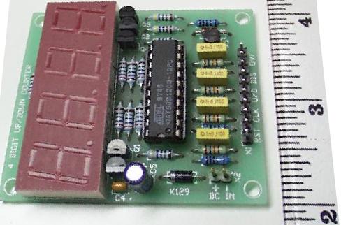
The vendor supplied description of the kit is as follows.
K129 - 4 Digit Up/Down Counter
Low cost 4 digit up/down counter using an Atmel 90S1200 AVR microcontroller.
Inputs include "Reset", "Count", "Count Direction" and "Disable". Also
has an "Overflow" output for connecting to another counter. Built in debounce
(10mS) for easy connection to mechanical contacts. Maximum count rate is
50 counts per second. 9-15VDC @ 100mA supply required (not supplied). Small
physical size: 52 x 61mm (2" x 2.4").
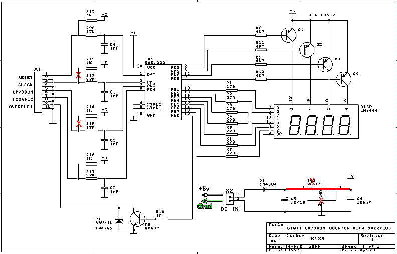
Above is the manufacturer's circuit schematic.
The necessary modifications to the K129 kit, as indicated on the schematic are:
Power to the counter is supplied from the regulated power of the stepper driver kit. The value of the pull-up resistors is too small to allow positive control of the counter by the supporting circuit, and they are redundant to the overall circuit.
NOTE: This kit is normally supplied with a built-in delay
to provide debounce for noisy switch pulses. The supplier [Frank Crivell,
frank@ozitronics.com] will happily remove the debounce for you. You must
ask to have "zero debounce" programed into your Kit when you order it,
or return it to Frank to have it re-programed.
WITH THE DEBOUNCE, THE COUNTER WILL FOLLOW ONLY ABOUT 10 PULSES
PER SECOND. THIS WILL NOT DO!
THE HAND PAD
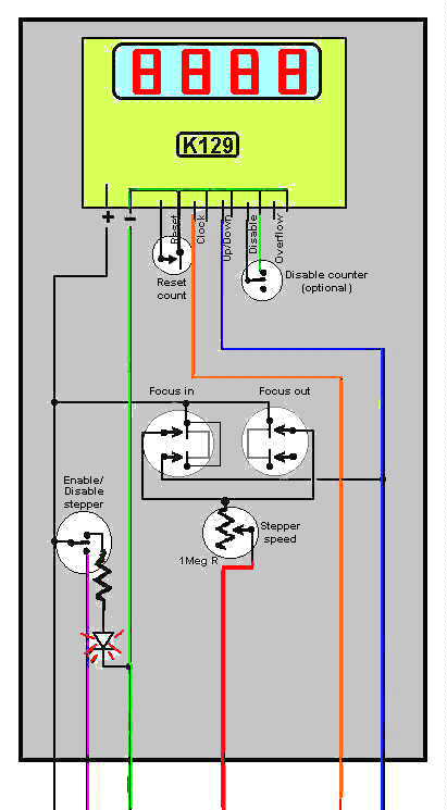
The illustration above shows the control circuit for the hand controller.
Color coded lines correspond to the connections on the stepper driver PCB,
as shown below.
The hand pad contains the counter and the control components.
It is built into a project box suitable for the hand pad. The
prototype is pictured below.
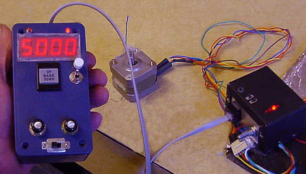
The prototype was constructed to include two speed control pots (fast & slow), a single-step momentary with a selecting toggle switch, the in/out run control switch (a DPDT center-off rocker switch), a slide switch (SPST) to disable the power to the motor, and a momentary push switch (SPST) for resetting the counter. I chose to have this counter programmed to reset to 5000. (The jury is still out on that decision.)
Using the prototype model, it became apparent that the controller could
be simplified considerably. A single 1 meg ohm potentiometer is quite
adequate to control the stepper speed. The speed control pot allows
slow enough pulsing that single stepping, as a separate function, is not
necessary. And finally, two separate momentary switches for in/out
run control are easier to operate than the single rocker switch.
The design provides control functions as follows:
The counter LED display is too wide to fit into a small hand box. You will have to look around for a box with enough width, that is still comfortable to handle.
6-wire telephone cable and RJ-25 connectors work well for connecting
the Hand Pad to the Stepper Driver.
THE DRIVER
The following is the vendor's description of the driver kit.
K109 - Unipolar Stepper Motor Driver kit
Drives any 5, 6 or 8 lead unipolar stepper motor. Based on the UCN5804
IC. All features of this IC (direction, on/off, phase control & half
step) are brought out to SPDT PCB-mounted switches. Pulses from a 555,
setup as an astable oscillator, are used to roughly position the motor.
Switch to manual single-step mode for final positioning using a push button
switch. 4 LED's give visual indication that a step has been made. Three
run modes supported. Full explanation & 5804 Data Sheet included. Stepper
motor not supplied
Below is the manufacture's schematic of the driver circuit. The
necessary modifications to the kit are shown. The 6 control lines
passed to the focus controller hand pad are shown color coded corresponding
to the lines at the hand pad.
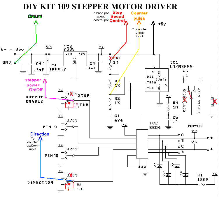
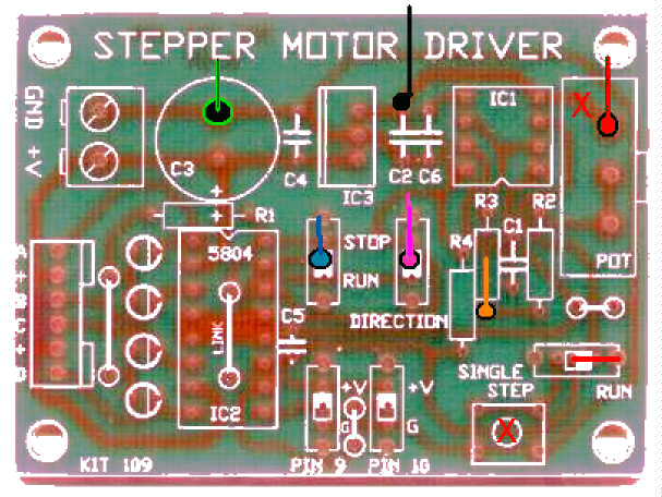
The needed modifications to the 109 kit are as follows:
The take-off points for the control and power lines are shown on the
picture of the circuit board below, again color coded for their corresponding
functions.
The controller works quite well. In playing with it, on occasion a switch press is dropped due to bad contact, inadequate pressure (?). This does not have a negative effect on performance since sequencing of the stepper and the counter is not lost.
The operational accuracy of the focus controller will depend on the mechanical performance of the focuser and stepper motor drive linkage. As with all other motion functions of a telescope, accuracy of operation depends primarily on the capacity of the mechanical components to perform with accuracy.
The following are reference links to the designer/manufacturer of the
two kits used in this project.
mailto:frank@ozitronics.com
http://www.ozitronics.com/
http://www.ozitronics.com/kitlist.html
HOME